Bigger, better, faster milling machine
After years of pushing my little X2 Mini-Mill to the limits, and trying to cut aluminium on my large router table, it became clear that I need a bigger machine, that can handle metal with decent precision. And of course it has to be CNC, and it should be a capable beast. Fast, precise, versatile.
Selecting the machine
After lots of searching on the web, and talking to a friend at the local makerspace, the Optimum MB4 came to my attention. And of course the recommendations of Stephan Gotteswinter add a lot of weight. After some good experiences with my Optimum lathe, I went to Stadelmann (swiss Optimum dealership) to have a look, and to compare it to the other OptiMills (BF30, etc.). Of course I packed my bag with dial indicators for rigidity testing.
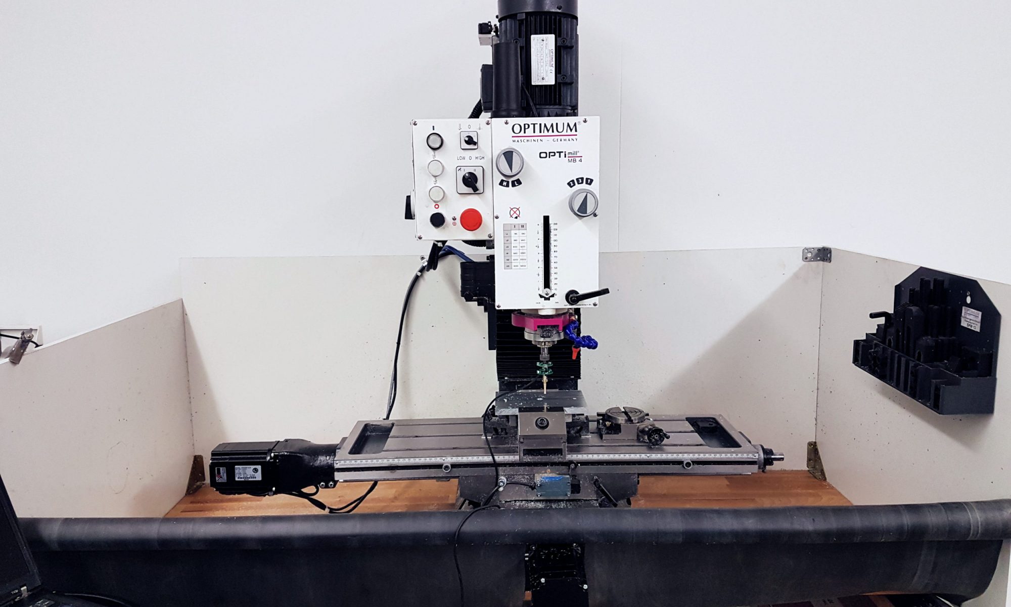
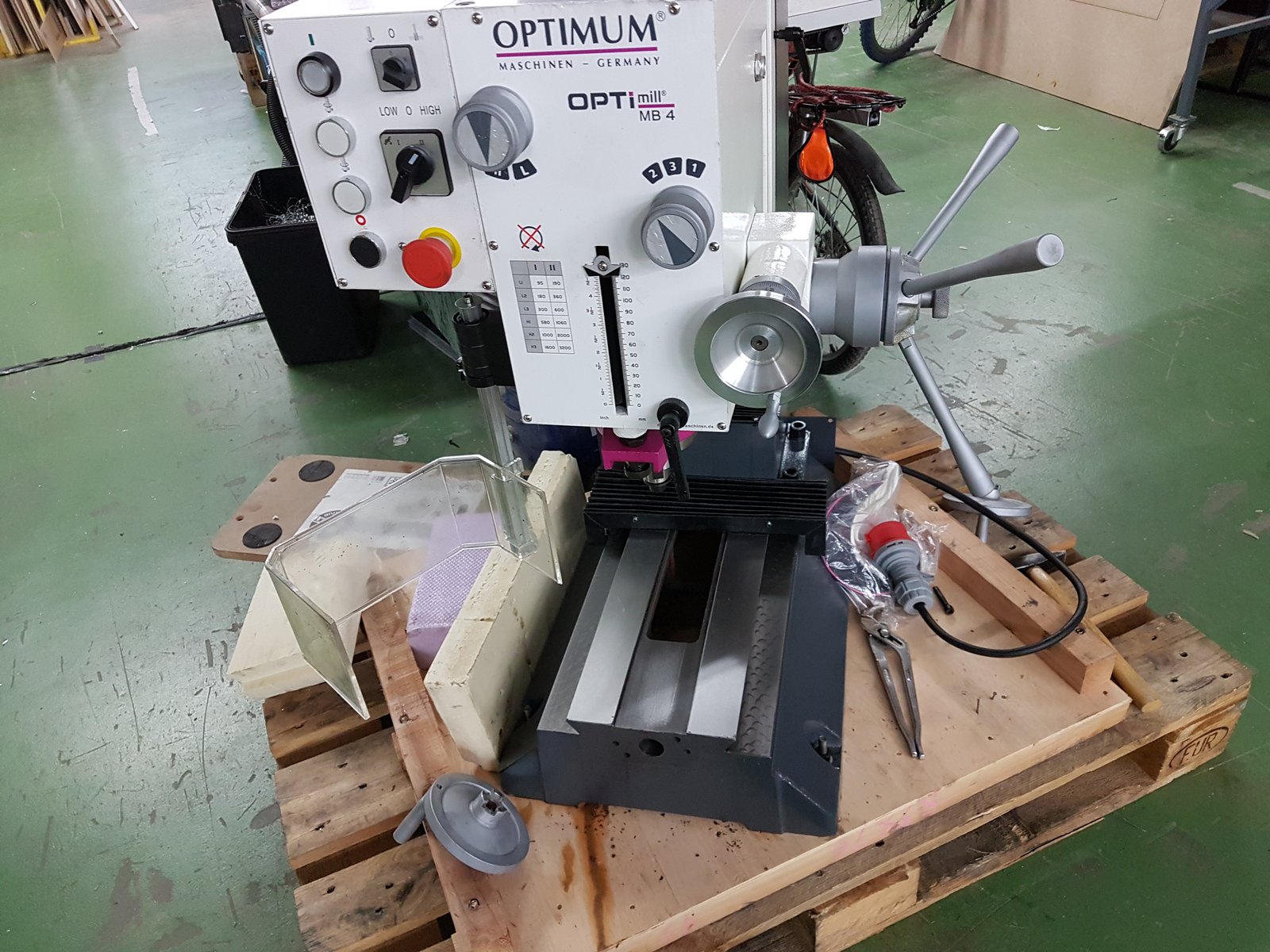
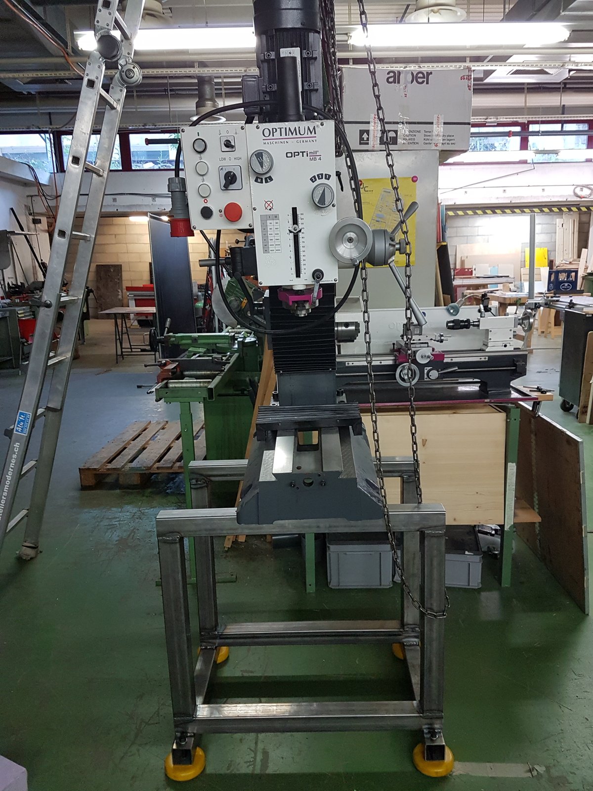
Here it is in the shop:
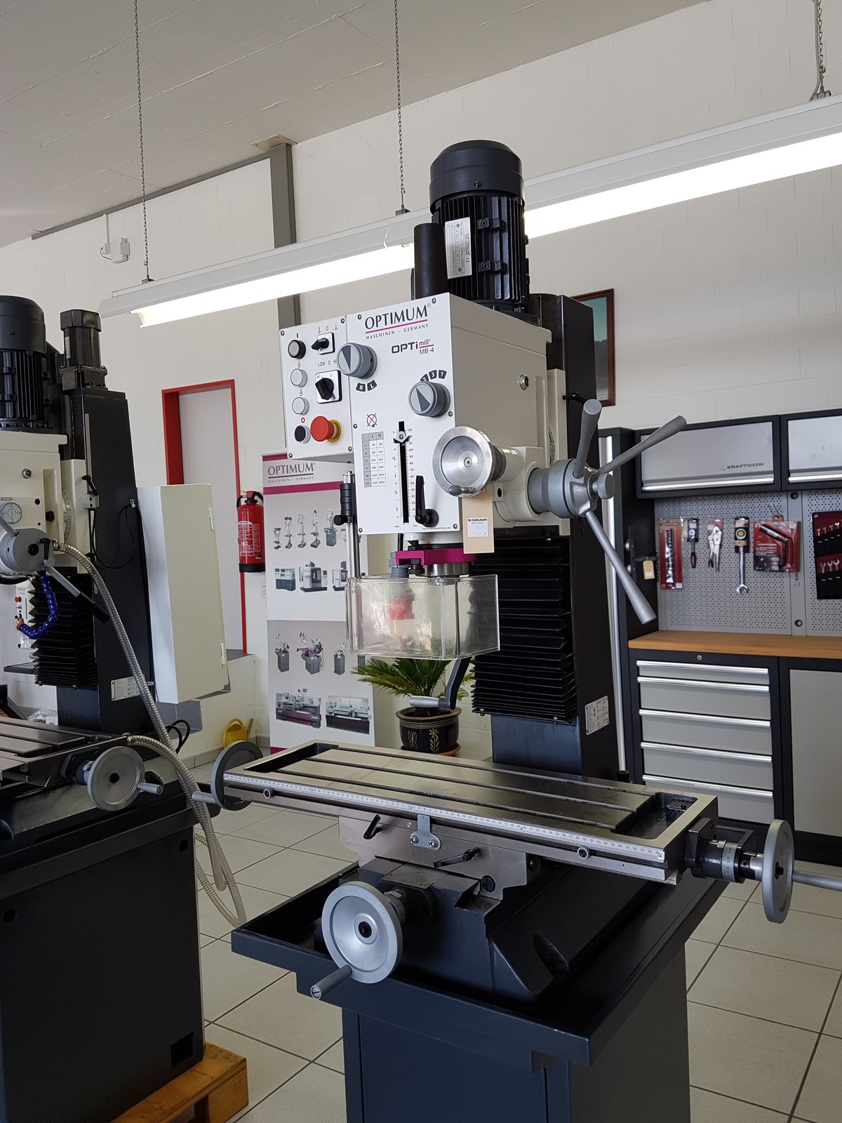
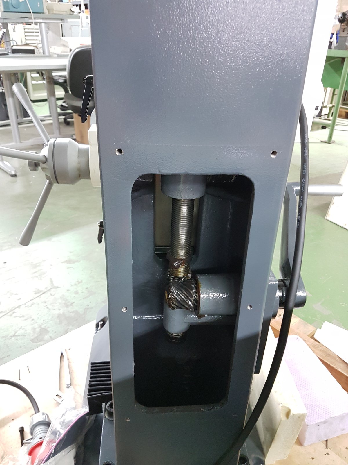
Compared to the BF30, which is roughly the same size, the MB4 definitely is the heftier, sturdier machine in any way. The deflection from spindle to bed (all ways locked down) with as much muscle I could muster was 0.02-0.03 mm, about half of the BF30, in this admittedly unscientific test. Just looking at the size of the Z-column explains this nicely though, it’s much fatter. The MB4 has a 6-speed gearbox, and a 2-speed selector for the 1.5kW motor, for a speed range from 80 RPM to 3200 RPM. While I like the vario drive on my lathe, and the BF30 offers Vario, I think having the super-lowspeed option is nice for tapping, and the gearbox will offer far more torque. The maximum speed of 3200RPM is a bit low for aluminium and small tools, but more on that later.
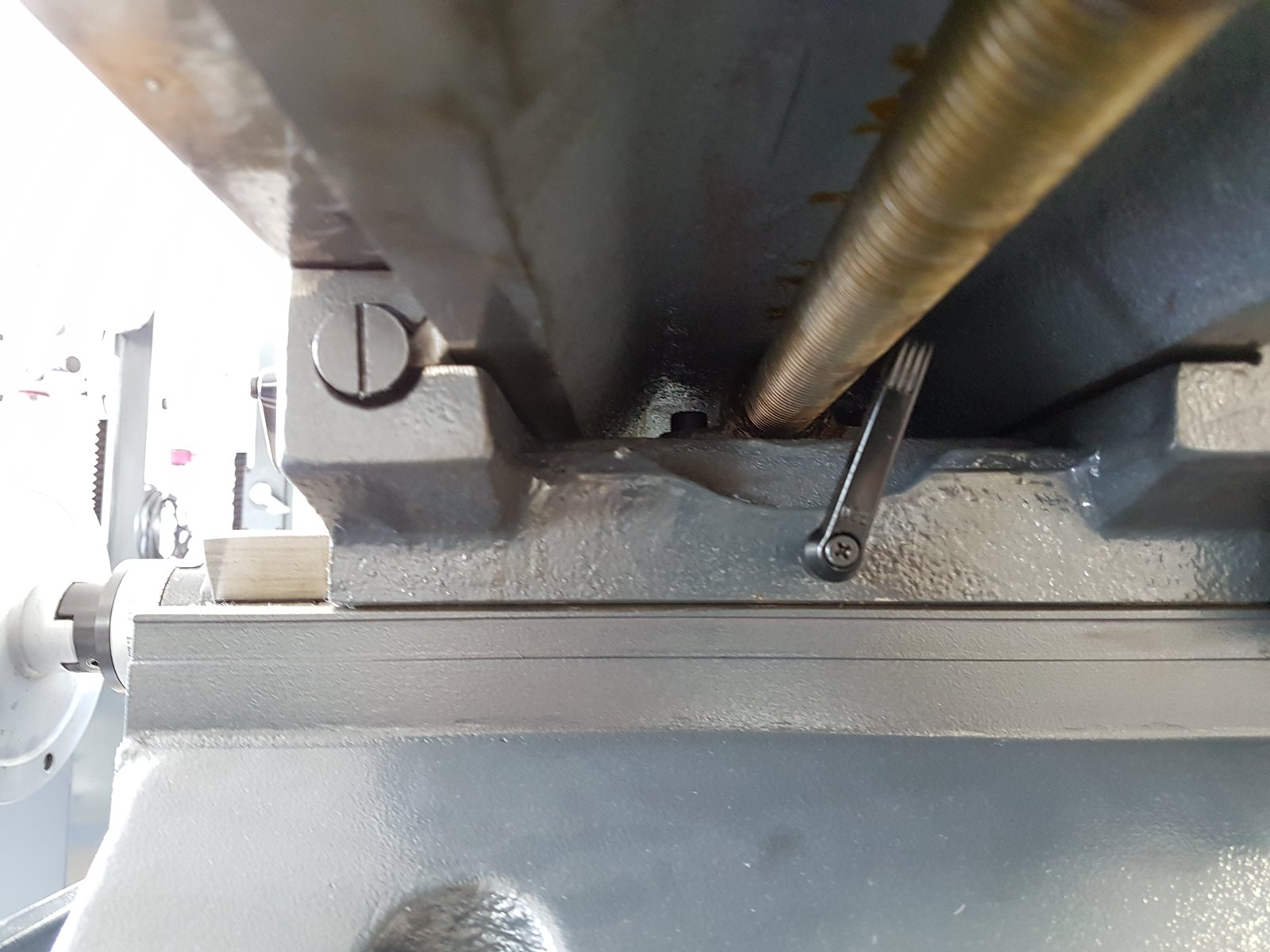
I also liked the 25mm lead screws, as this would allow me to put in some hefty 25mm ballscrews. The big advantage of the BF30 is that there is an official CNC conversion kit available. However, it is quite expensive, particularly when also buying the optional ballscrews (and a CNC mill without ballscrews is hardly worth doing). So I decided to go with the bigger machine, and do the conversion myself. The MB4 is also the less expensive machine, another plus.
Delivery and setup
The machine was delivered fairly quickly after ordering. Time to take it apart! 🙂
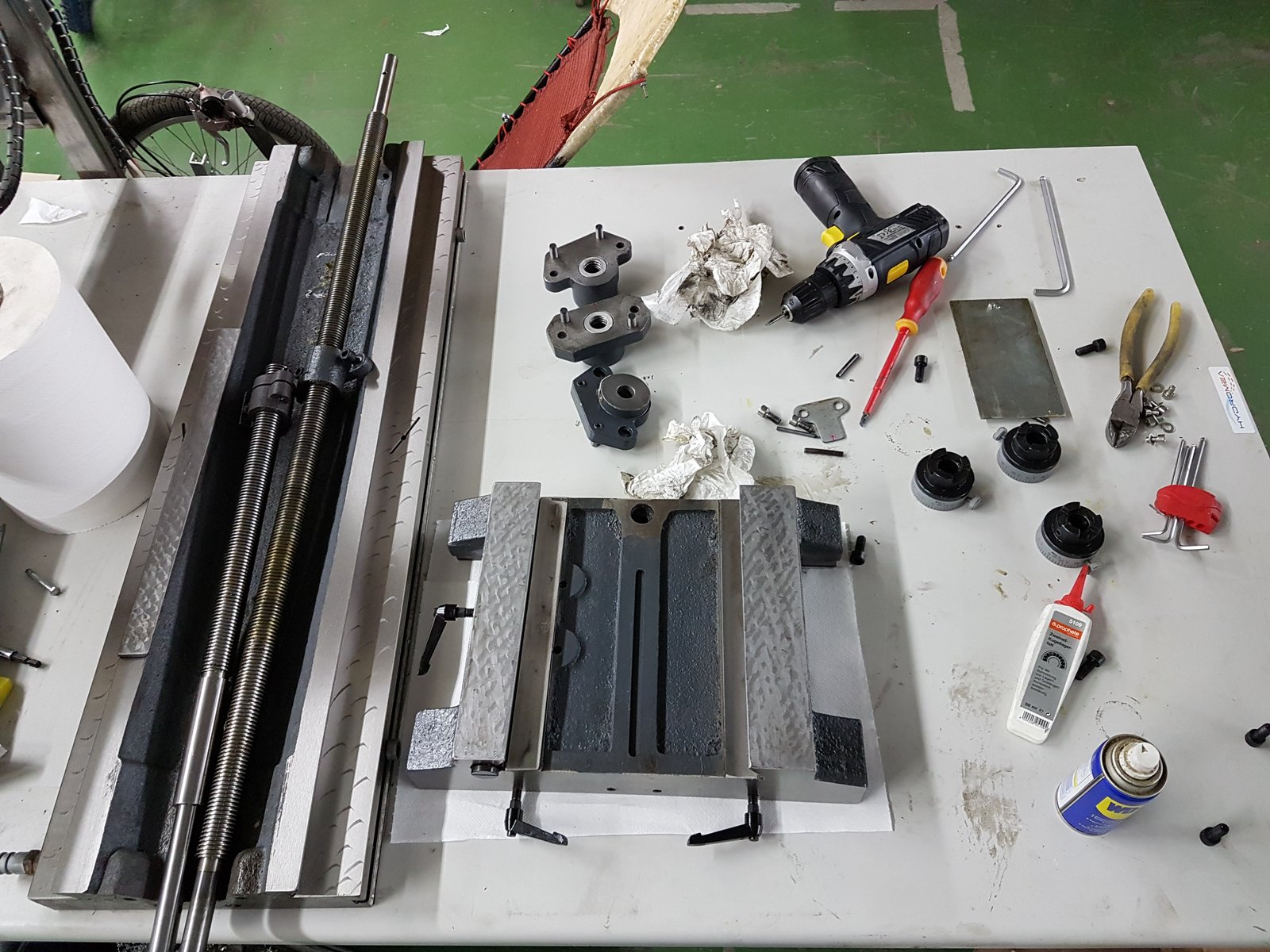
The parts looked pretty good. Following GTWR’s advice, a quick deburr and thorough cleaning is always a good idea. Next: taking measurements, creating a CAD model, and designing the parts for the conversion. While that is happening, I also welded a solid base for it. I didn’t like the base offered with the mill – not much storage space, and you can’t get a pallet jack underneath. So I built my own:
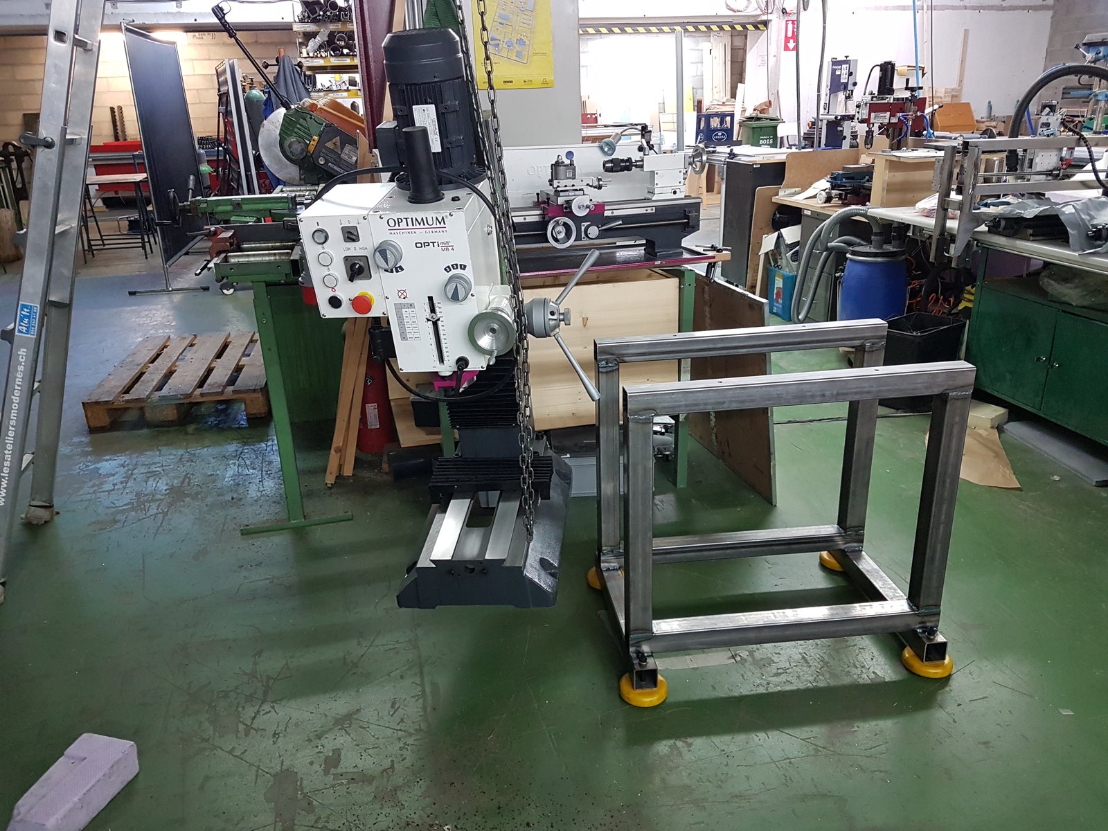
(continued in part 2)
Look like a nice project. Did you get it working?
Hi, thanks for stopping by!
Yes, it’s working quite well, I just hadn’t had the time yet to finish the write up. But more will follow!
Hi, looks a great project.
I just bought n MB4 this month, could you pls suggest motor type an size?
Thanks
I really should finish the write-up of this… unfortunately I’m quite busy with work right now. For the CNC drives, I use NEMA34 hybrid servos from AliExpress (closed loop with encoder). They work really well, rapids up to 6000mm/min. I also replaced the leadscrews with 2505 ballscrews. I hope this helps, and hopefully I’ll get around to write up the rest soon…
Hello,
I am looking for a heavy mill to work with steel and my favorite is the MB4. I want to convert the machine to CNC and would really interested in your write up.
Did you have to modify the bed to install the ballscrews or could they are mounted without milling the bed? I have only a CNC mill out of aluminum and can’t really milling the heavy bed of the MB4 and hope ball screws could be mounted without heavy modifications.
Do you have pics from the conversation?
Best regards,
Jan
Hi,
thanks for your interest! Good timing – I was actually just writing part 2, with CAD models, BOM and lots of pictures of the build. It should be up on the site now.
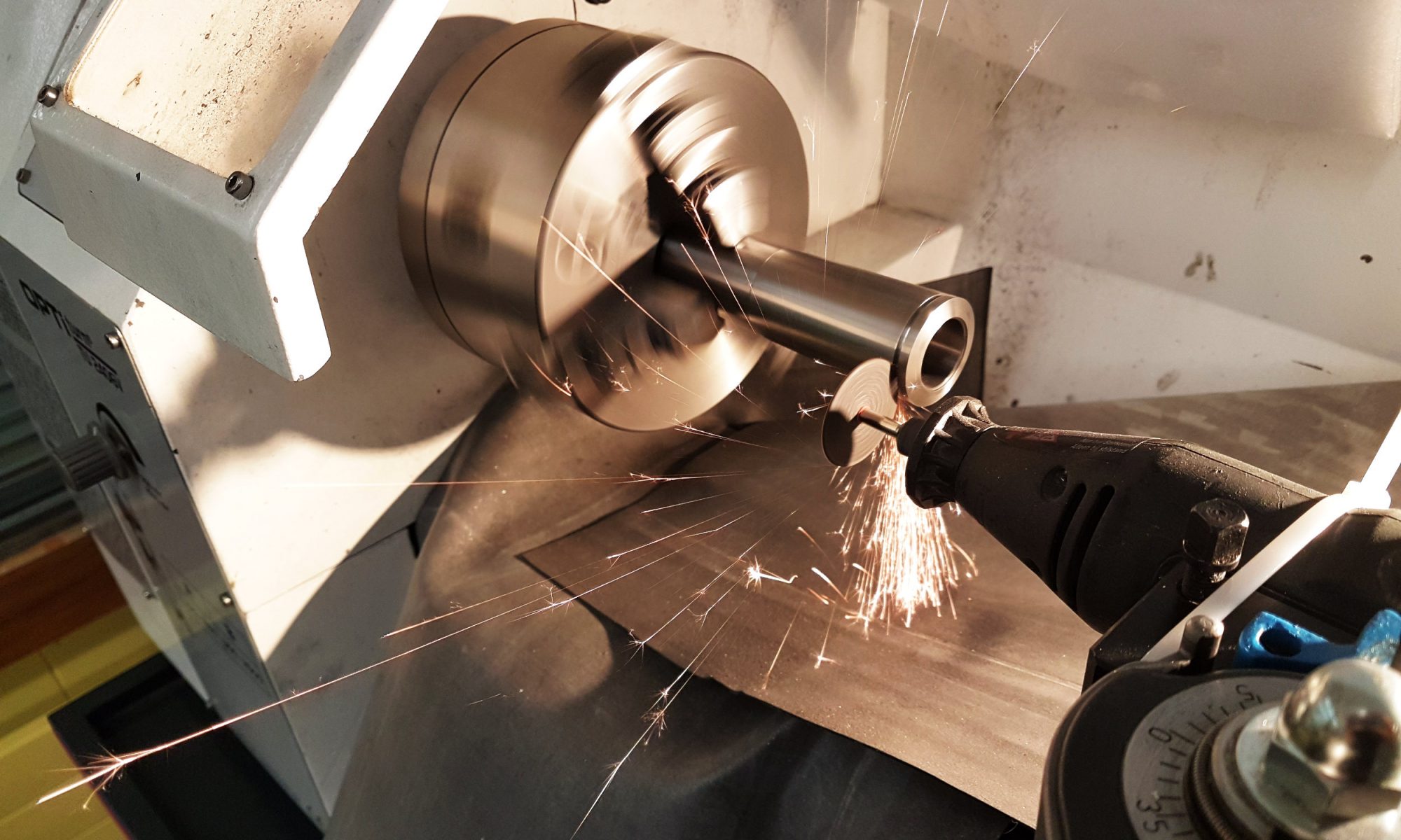
I only did some very minor modifications on the MB4 itself, all of them on a tiny X2 mini mill. I flattened one spot of the Y axis to allow the ball screw to sit a bit better, but I think it would have been possible to do it without that, by changing the ballscrew mounting piece a bit or grinding off the flange on the ball nut a bit more (you’ll see, I did have to do a bit of grinding to fit 2505 screws). I hope part 2 will answer your questions.
I’m very happy so far with the MB4. It’s a solid machine. I did have a little bit of stick-slip on the Z axis (about 0.05-0.1mm), which I think was due to a badly matched gib on my machine (slightly wrong angle in the taper). It is probably also an issue caused by the big front-heavy head. Some people reported to have fixed it with gas springs or counter weights. Of course it’s not an issue for manual machining. For now I fixed it by adding backlash compensation in the software, and it doesn’t bother me that much for what I do. I haven’t measured in a while if it’s still there after running in. The X and Y axis are very good. I also changed the grease in the main spindle bearings, as they got a bit too hot for my taste. I think with these machines there can be minor issues here and there, that some people have and others don’t. But all in all I think the MB4 is great, and at a good price. Looking at the BF30 in the dealership, the MB4 is definitely a lot sturdier and more rigid.
Brilliant ! Thank you for the detailed documentation of your project. I’m keen to convert my MB4 to ball screws, possibly with a CNC conversion in the future, but more for what I perceive as smoothness and better feel as a manual mill. Have you tried while building this, to crank it with the handles as a manual machine ? I’m curious if there is an improvement in feel, ease ? Is there a loss of fine movement, as I think the ball screws are moving 5mm per rotation v’s 3mm for the std lead screws ?
What did you do about the end/support bearings ? From your pics it looks like you used the original thrust bearings and mountings with no radial bearings ? I see with many of the ball screw suppliers, they have bearing kit/block that you’d have to mount in there.
Thank you 🙂
David
Hi David,
thanks for the nice feedback!
Yes, I did try to turn the handles with ball screws mounted, and it’s very smooth as one would expect. I can actually still put a hand wheel on the right side of X (motor is on the left), but the motor adds a lot of resistance so it’s not very smooth like that. I was originally planning to keep the option to use it as a manual machine, but for the Y and Z axis it would have been too complicated. I often use it “semi-manually” by jogging and positioning it through LinuxCNC, which then also has the advantage of offering a “digital readout” and consistent motor feeds.
I would say, using ballscrews is probably a bit smoother than the original leadscrews, but that depends a lot on the quality of the original screws as well, and how tightly they are adjusted. For a manual machine, one can leave them a bit loose and accept a bit of backlash, which will reduce friction. Then there’s probably not much of a difference. The main reason for ballscrews is to eliminate backlash – this is also nice for manual machining, but with DROs maybe less important now. One major difference maybe is that ballscrews can be back-driven. This could be a good or a bad thing – for machining fine features with small tools, maybe it will give better feedback. But with big tools, I’m wondering now if it would be counter-productive if the handwheel “kicks back” when the cutter engages.
5mm vs. 3mm – I suppose you’d lose a bit of resolution, but it probably doesn’t make that much of a difference. The diameter of the handwheel, and how steady your hands are, also come into play. I actually have a small Mini-mill with 1605 screws and steppers, and often used it manually, but then I also never really did manual precision work on that one so I can’t say.
The support bearings are all still the original ones, so it’s a pair of thrust bearings, and I think just a bushing on the opposite side. It seems to work just fine. The thrust bearings do have a bit of a groove, and when loaded will also provide some amount of radial support. And as I’m driving them with a motor, there shouldn’t really be any radial loads on the screw anyway. The bearing blocks from suppliers have bearings that look like radial bearings – I assume they’re deep-groove bearings. For thrust, I would imagine that they’re not as good as proper thrust bearings, or angular contact bearings, but I’m not an expert for that. There’s probably also a big difference if the blocks are cheap chinese no-name, or high-quality brands for 10x the cost.
Thumb up! Great conversation. Are you happy with the selected torque of the servos?
Best regards!
Michael
Yes, the servos are awesome, and plenty powerful for this machine. The rapid speed is currently 5000mm/min. I had it on 6000mm/min first, but found it to fast for manual jogging (a bit scary to an amateur like me…), so I reduced it to 5000. I think the limitation is rather the spindle power, not the servo feeds.
Great project!
I am planning to use also this mill for my project. I hope you don’t mind if I ask you some questions 🙂
Do you think going with 20mm ballscrews for the XY is strong enough?
Do you think a 32mm Z will fit?
How much travel did you get at the end? is there still room for a larger Y?
Are you planning to use a belt-driven spindle later?
Do you find the MT4 suitable for CNC?
Last but not least, when is part 3 coming? =)
Kind regards and thanks in advance!
Pablo
Do you think going with 20mm ballscrews for the XY is strong enough?
I think 20mm would be sufficient. I’ve seen commercial conversions of similar sized machines (e.g. BF30) that use 20mm screws. I went with 25mm as it was possible (bigger is better…), but it ended up a bit difficult. I had to grind the flanges on both X and Y ball nuts to make them fit properly.
Do you think a 32mm Z will fit?
Not the way I did it, using the existing mounting sleeve for the head – that will just fit a 25mm screw. If you make your own adapter, it might work. The column has plenty of space.
How much travel did you get at the end? is there still room for a larger Y?
I have 195mm travel on Y now, allowing for a little bit of “over-travel” (the cross-sled going beyond the edge of the base). I had to cut off a bit of my motor mount to allow for that, but there wasn’t a problem with the ball screw. The limit is just the slider hitting the motor mount for now, so it could be improved further with a different thrust bearing block and motor mount design.
Are you planning to use a belt-driven spindle later?
No, but I did put in a 24k spindle from AliExpress with an adapter sleeve, which works really well for aluminium. Wanted to make a video one day showing that, but have so little time…
Do you find the MT4 suitable for CNC?
Yes, I’m very happy with my conversion. The cast iron is a lot chunkier than other Opti machines in that size, everything is super solid. I have essentially zero backlash on X and Y. On Z I was struggling a bit with stick-slip for a while, leading to a little backlash. I think it was a combination of a bad gib (angle slightly off) which caused more friction than usual, and also some tension in my ballscrew as I didn’t mount it correctly. Others with the same machine don’t have this problem, so it was probably just my particular machine.
Last but not least, when is part 3 coming? =)
ah, so little time… but I’ll try my best 🙂
Thanks for sharing your Optimill MB4 CNC conversion project. I’m planning doing it myself now however I don’t have a mill now so I need to 3D print al the X/Y axis bsholder, Z-axis bearing mount and motor holders until I can CNC mill them myself. Do you have some recommended 3D print settings? 100% infill seems like a given.
Kind regards
Finn