(continued from part 1)
Time to make some drawings! I took some rough measurements and built a CAD model, to be able to plan out the parts for the conversion:
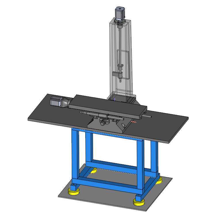
(Warning: The CAD model is only an approximation, and I did have to do some manual tweaks to my parts to make them fit properly. Use at your own risk – it’s only meant as an inspiration and starting point.)
Based on the CAD, I decided to use 25mm ballscrews with double nut on X and Y, and with a single nut on Z. My thought was that the Z axis is under unidirectional load anyway (head pushing down with 80 kg), so backlash will not be a concern here.
Ordering the parts
For the motors, I decided to go with closed-loop servo drives, in NEMA32 size. They are not that expensive any more (at least the chinese versions), and the work well. Much faster than equivalent steppers, and more reliable. They will not loose steps, and even if they get jammed (e.g. when running into a fixture), there is an overload output signal that can feed into the E-stop of the controller, safely halting the machine.
I picked two 8 Nm motors for X and Y, and a 12 Nm motor for the Z axis, as it has to hold a lot of weight. The head of the MB4 weighs around 80 kg. The motors cost around $200 each, including the matched servo controller (2HSS86H). See the BOM above for details.
I ordered the ballscrews from Noulei (via AliExpress), and had them custom-machined to my specifications. The sellers usually do this happily for a very small fee. Here is the drawing:
The custom parts
Finally the hard part: making it all fit together, or rather, making the connecting pieces that will make it all fit. I tried to avoid modifying the machine as much as possible. It didn’t end up a complete bolt-on kit, but the modifications were fairly minimal. It does require machines to make the parts though – luckily I already had my X2 mini mill (CNC converted) to do that. It struggled a bit, and I thought it would have been a lot nicer to do that on the new OptiMB4, but it wasn’t CNC yet…
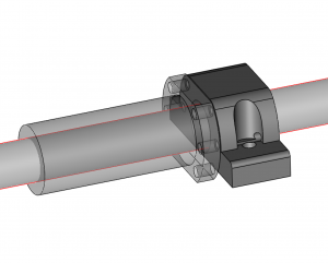
I designed four pieces: The X-Axis ball nut block, the Y-Axis ball nut block, the Z-axis top bearing assembly, and a motor mount for the NEMA34 servos. The cad files are in the zip archive linked above.
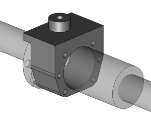
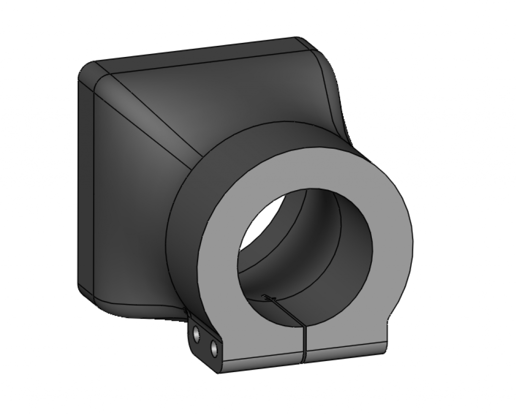
Note that my initial design of the ball nut blocks didn’t quite fit. I had to trim them down a bit to fit into the available space under the X-axis bed, and into the channel in the base. The cast iron pieces had some tapers that I didn’t quite capture precisely in the CAD. I updated the CAD slightly to reflect this, but I can’t guarantee that these will fit perfectly.
I machined the first three pieces from aluminium. The motor mount is far too big for my little X2 mill, so I 3D-printed it.
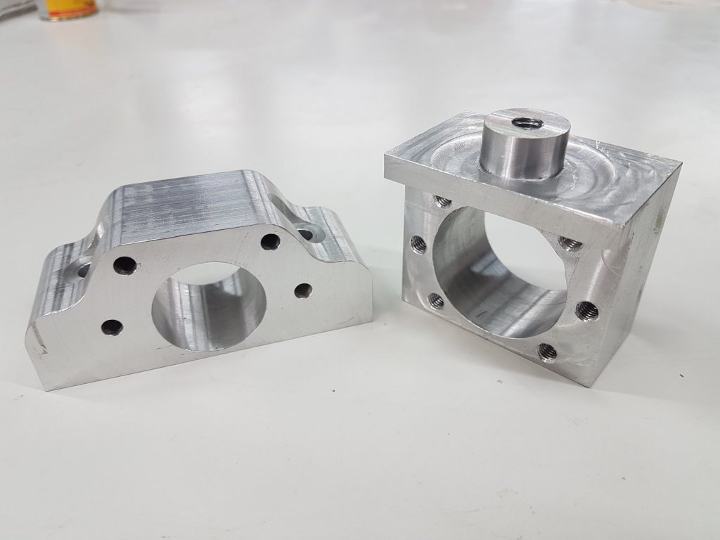
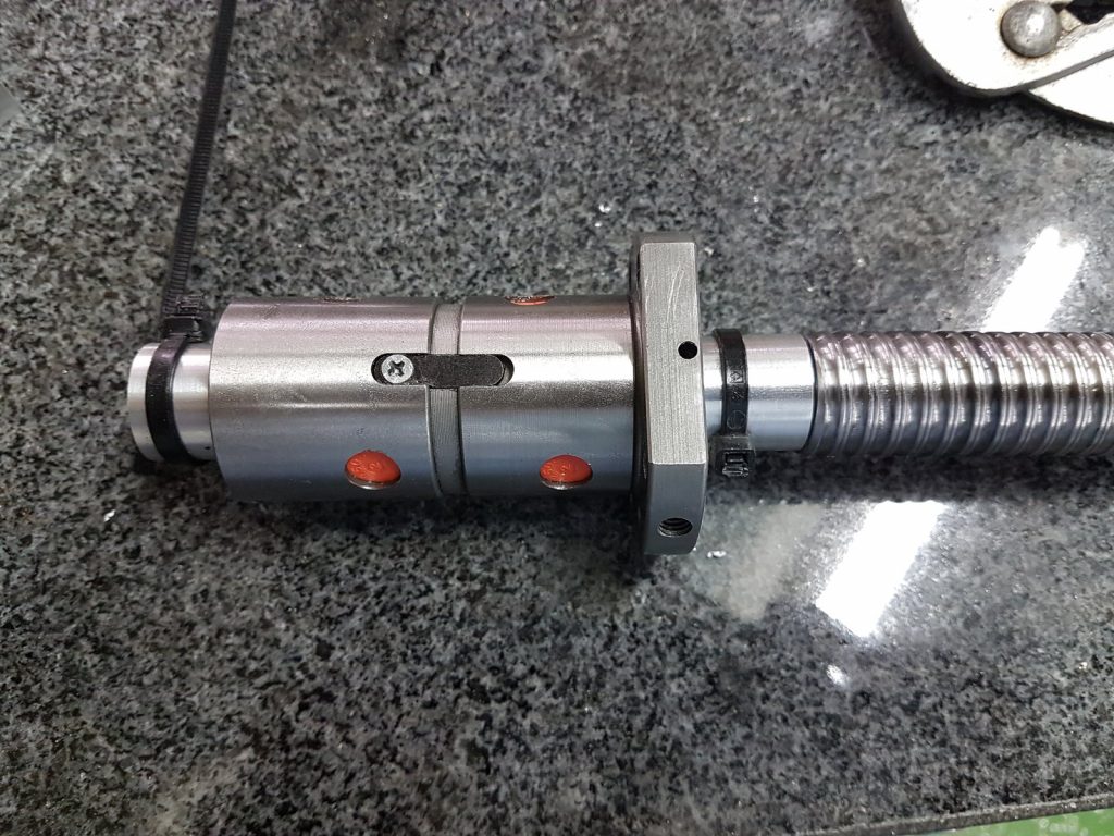
When test fitting the ballscrews, I noticed that the channel in the base was a bit too narrow in some spots for the ball nut to fit. It didn’t take much, so I decided to carefully grind off the flange a little until it fit. Similarly, I had to do the same for the X-axis ball nut. This probably could have been avoided by going with 20mm ballscrews, but I think a bit of grinding is fine to get the larger ones (and also, I had already bought them at this point, of course…).
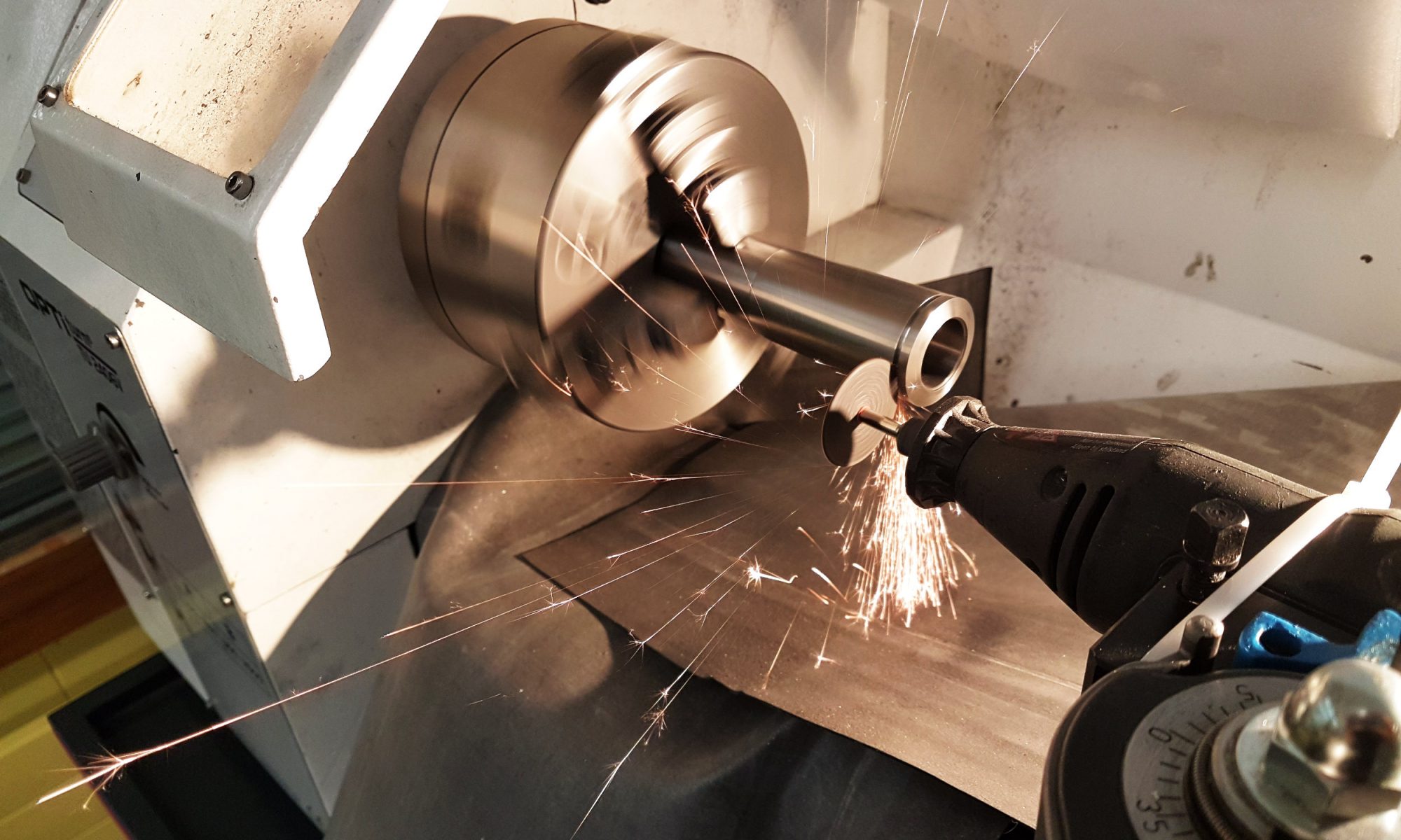
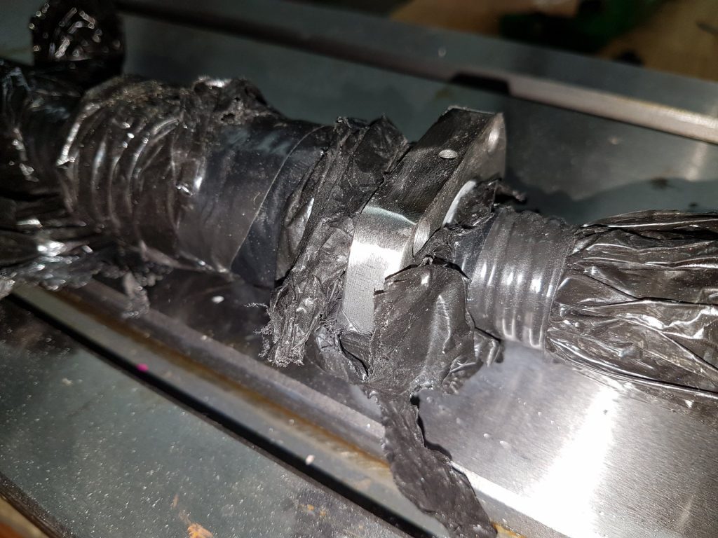
I also had to flip the ball nut on the y axis scew. For this, I made a transfer sleeve on the lathe. Don’t ever pull a ball nut off the screw without it, and make sure it’s a tight fit! I have already botched this one once, on a very nice precision ground screw, and trying to get all the balls back in was not much fun…
Now the same for the X axis:
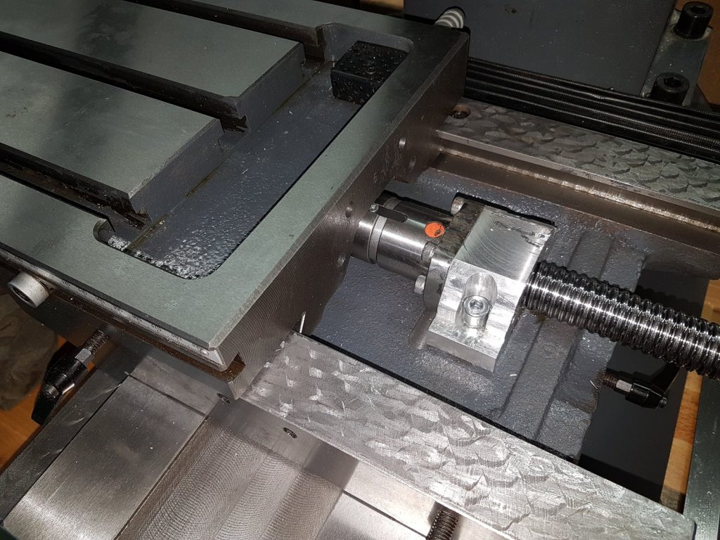
So now the two ballscrews are mounted, and a lot of the hard part is done. As the ballscrews didn’t quite end up on the same height as the lead screws, I had to modify the original bearing blocks a little bit, to be able to slide them up and down to get proper alignment. I simply turned the screw holes into slots.
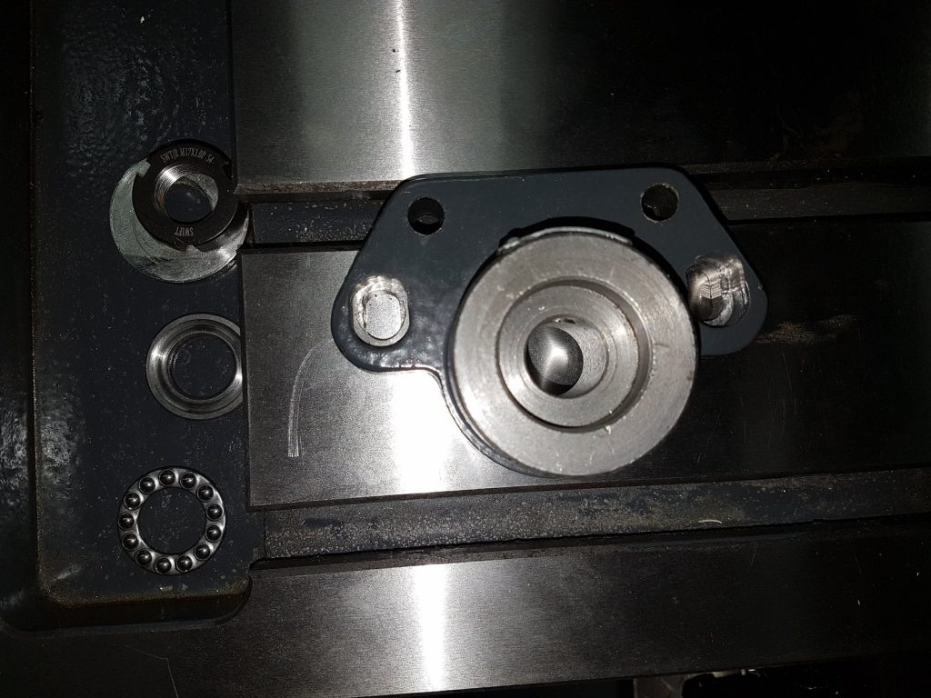
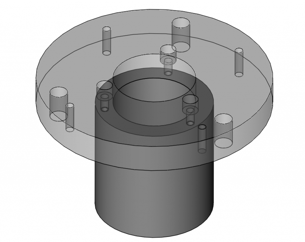
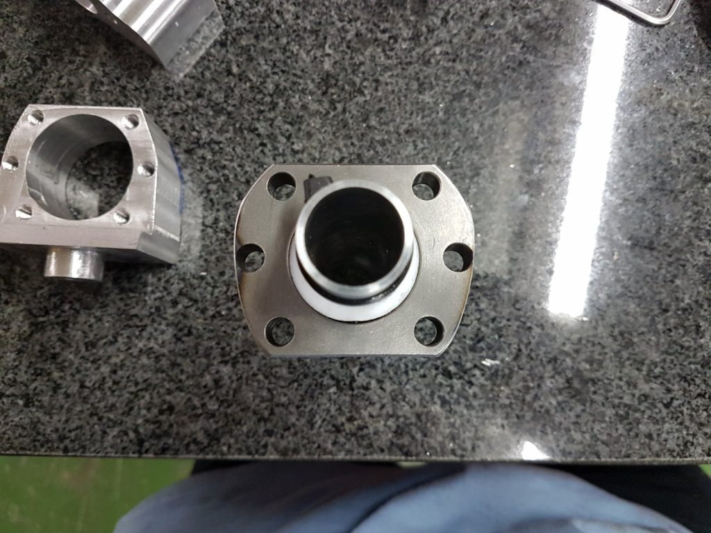
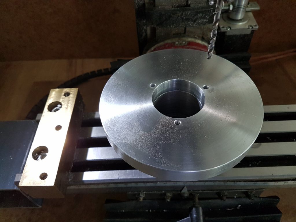
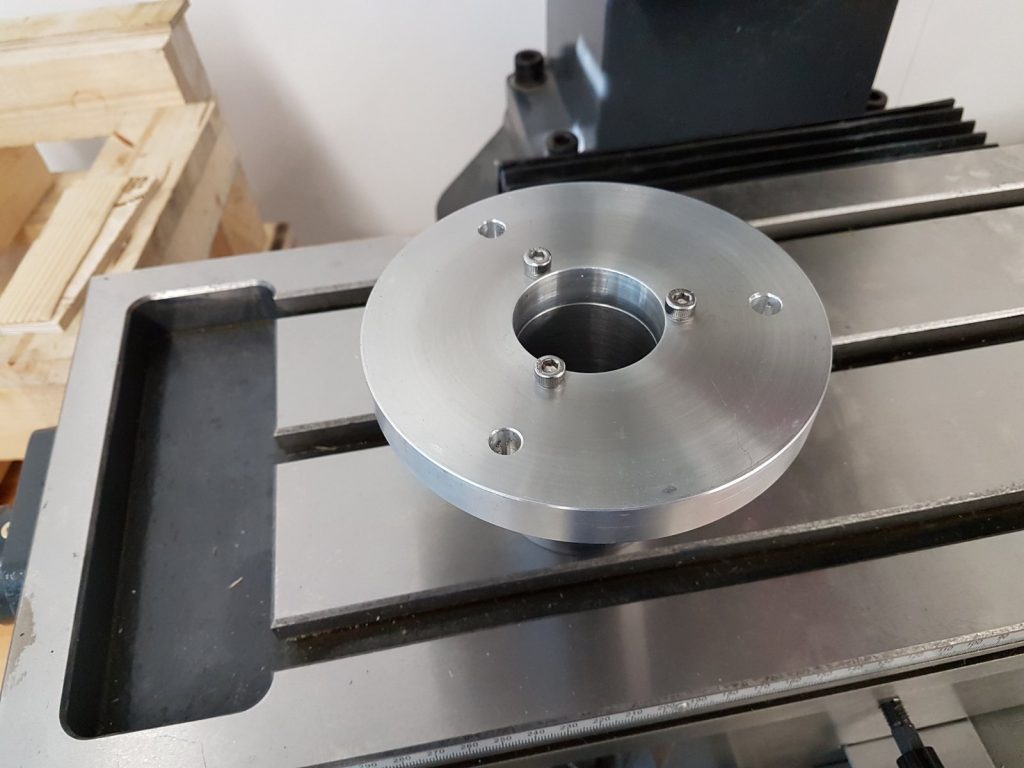
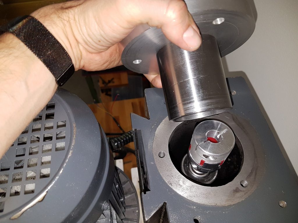
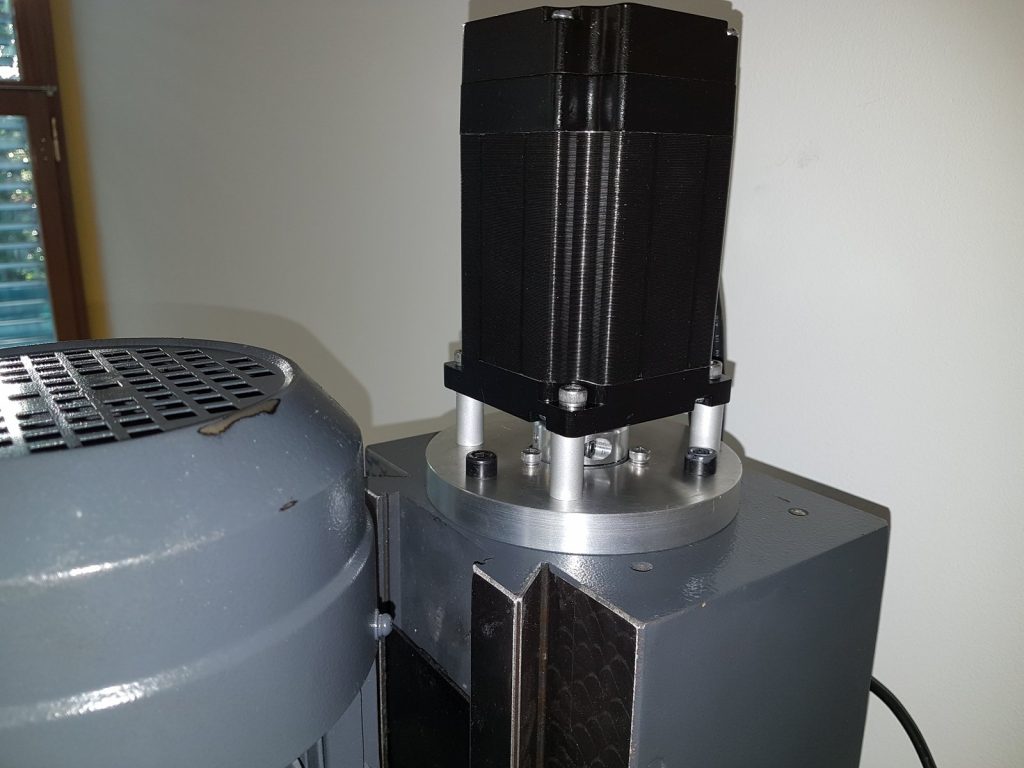
Next I made a new top cover plate for the Z axis. The MB4 has a geared crank on the side of the column, which turns the z lead screw. The top cover has a sleeve bearing to hold the lead screw, but it is closed. I had decided to put the Z motor on top of the column, so I needed a new cover with a hole, and a support bearing. I started by turning a new cover plate:
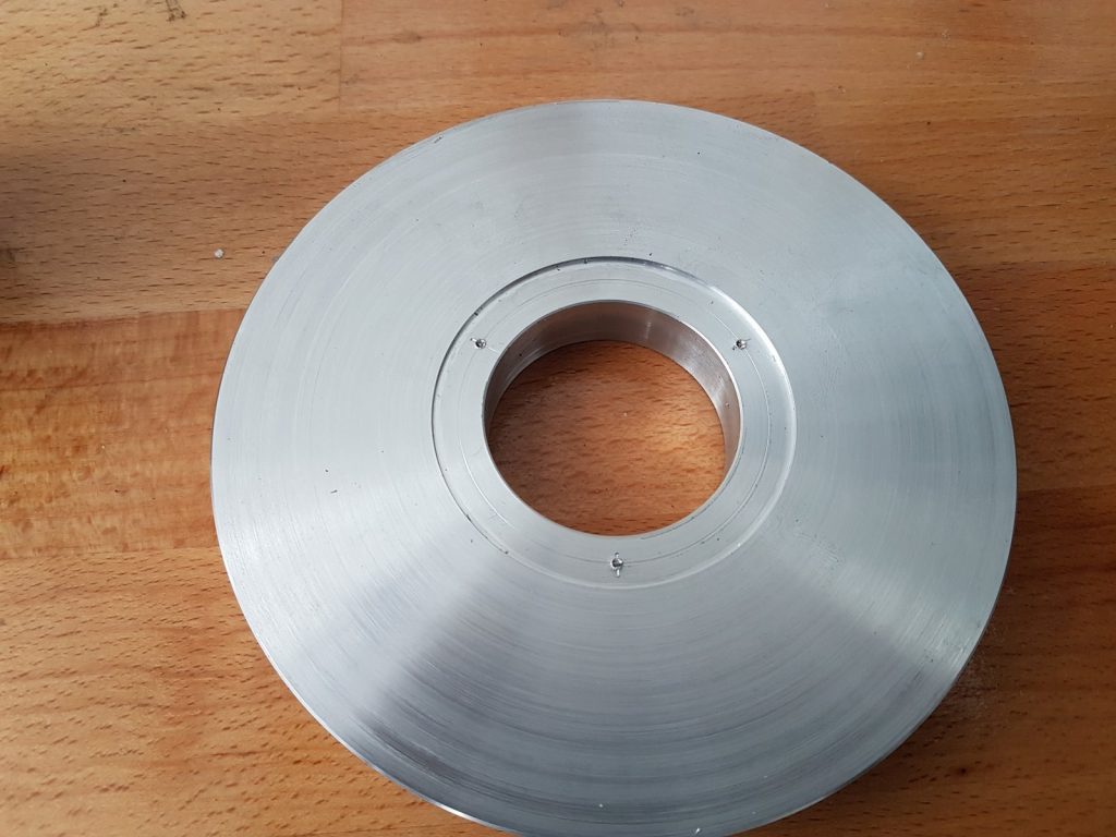
While I had it in the lathe, I already marked out the radius for the bolt holes, by just touching it with a lathe tool and turning the chuck one revolution to make a small scratch. I then marked out the hole positions on that line.
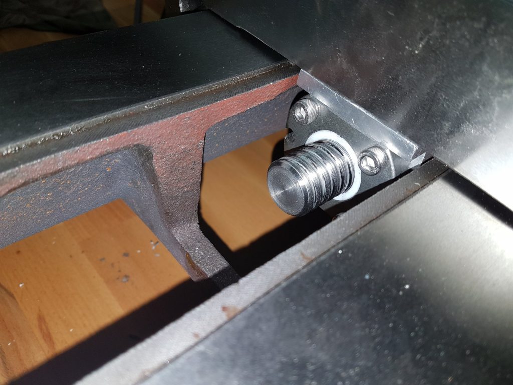
Installing the Z axis ball screw
The difficulty in replacing the Z axis lead screw is that it holds up the heavy head. By locking the gibs, it is however possible to hold the head in place while taking the load off the screw to be able to remove it. I also made a wooden support structure to support the head in the low position, which is not really needed for this part, but comes in handy when removing the head from the Z axis. You can simply lower the head on the support block that rests on the table, then unscrew it from the column and use the Y axis to slowly move it forward.
The Z ballscrew was designed to fit in place of the old lead screw, using the existing bearings and mounts. The block that connects the screw to the head assembly slides out easily (it is just loosely pushed in). I removed it, drilled and tapped holes to bolt the ball nut onto it from underneath. Unfortunately I didn’t take photos of this part.
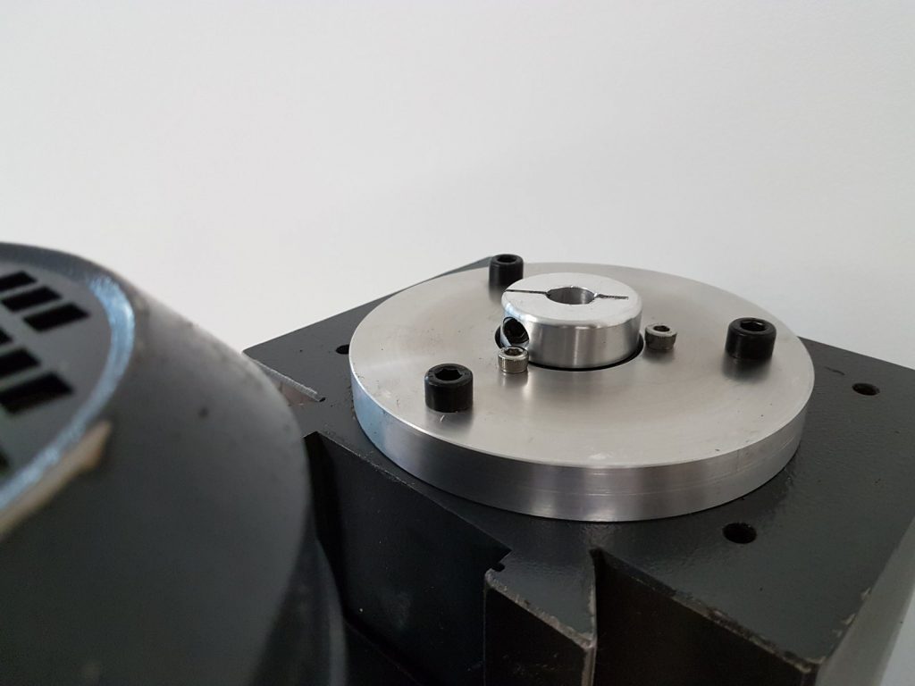
Once the ballscrew is in place, the top cover can be installed.
Motor mounts for X and Y
The motor mounts for the X and Y axis were quite big, and too much of a job to do on a tiny X2 mini mill. I decided to 3D print them, but was worried about strength. I had an idea to cut on printing time, and get better strength:
I printed the part with zero infill, on a low-cost FDM printer (i3 clone), with a 0.8mm nozzle. Printing with large nozzles dramatically increases the print speed, and I find that the layer adhesion is often better – probably because the larger amount of plastic has more residual heat, which makes it stick better. The part is then of course hollow and not very strong.
As a second step, i drilled some holes into the top, mixed a 2-part polyurethane resin with chopped carbon fibre strands (2mm), and filled the entire part with this resin. After curing, it was really strong, as the infill is all one solid cured block with fibre reinforcing.
The motor mounts are simply clamped onto the existing thrust bearing blocks that came with the machine. So far it has not let me down.
So this is more or less it for the mechanical parts. Next: Wiring it up.
Great Job MAKER,
well done, well documented, god bless you 🙂
I’ll start with mine in spring, to busy this period, and let you know.
May i just ask you to check the ballscrew drawing download, doesn’t work.
Thanks for your effort
Fabrizio
Fixed the link, thanks for pointing it out. Good luck!
Guys i am really waiting for new news from you. 🙂 my MB4 coming in a few days. but i dont even know how to place it on the table 🙂 but in plans to convert it to cnc. Thanks for sharing dear Sirs.
Great to hear, and good luck with the setup! When I first got my machine, I was lucky that I could use a chain hoist from a ceiling beam to lift it onto the stand. I later had to move, and just took it all apart for easier transport and lifting. I built a wooden support for the head, to set it down onto the bed – this makes it easy to unscrew and pull it off. The heaviest parts are the base with Z-column, and the gearbox head assembly (around 80kg). Two people working together can lift it.
hello, congratulations for your design!!
i am traying to edit the files with fusion 360, but is not possible.
do you know how to do it?. thanks
regards
Hi Alberto,
not sure, I don’t have Fusion on this computer at the moment. You would want to import the .stp (STEP) files – it’s a pretty standard format, and Fusion should be able to open them. I vaguely remember that there isn’t a straight “Import” feature, but something like “new design from file” which allows you to load an external file to import. I hope this helps!
hi,
how much movement do you have in the y axes?
does the ball nut touch at the end with the base limiting the movement of this axis?
regards
I think it’s 195mm at the moment. The limit is the clamped-on motor mount, actually, as the y-axis block moves beyond the base on the front in the original design, and moves over the bearing assembly. The way I clamped on the motor mounts around them means that it hits the mount at some point. In the back, it’s the concertina covers that limit the movement – I think I could go a few centimetres further without them, but I’m not 100% sure how much ballscrew travel I have left.
The mechanical part of a cnc milli only half of the conversion requirements. What cnc controller, drives, and so on, are you using or planing to use.
Nice work.
I am using closed-loop hybrid steppers (NEMA34) from AliExpress. The motion control is done through LinuxCNC with an old-fashioned parallel port breakout. Works quite well, but recently I noticed that LinuxCNC has a lot of trouble with newer versions. I’m still using the RTAI kernel which is very outdated now. The new RT preempt versions that use the native Linux kernel realtime extensions doesn’t work for me – way to much jitter. I think I’ll start looking into external motion control cards at some point. For now it works though.
Hi, i have also upgraded my MB4 with some NEMA34 Hibrid stepper. This works great but still with the ACME leads.
Have you the final drawing of the ballscrews? Which changes have you realised and would made after finish?
Thanks
Hi,
the drawing linked in the article for the ballscrews themselves is still the same – that’s how I ordered them, and I didn’t modify the screws. But I did have to grind off parts of the flange on the ball nut. I have a video on youtube that shows it in a bit more detail: https://www.youtube.com/watch?v=aAPB6wak00w
Also, the x-axis ball nut adapter needed to be modified a bit, as it caught on the table. I didn’t make new drawings of this though, sorry – I just machined and ground the part until it fit, and called it a day… I hope this info helps.
Great! Thank you very much!
Would you recommend keep the 25mm Ballscrew or the 20mm version also would works fine? Maybe easier to fit?
I guess some things could be easier with 20mm ballscrews (the flanges would fit a lot better, no need for grinding them off, etc.). I’m not sure if the original thrust bearing blocks would still work – I went with 25mm as it matched the original ACME screws. And I thought it’s nice to have something really fat and solid in there – but honestly I don’t know if the difference between 25mm and 20mm matters much. The screws are probably not the weakest link in terms of overall rigidity, I suspect the mounting blocks and thrust bearings are.
If the 20mm don’t have enough meat to fit, I guess the easiest would be to turn adapter sleeves (less effort than making new bearing blocks, if you have a lathe).
Hi, could you please share more details or information about the adaptation of the Z axis?