In this post, we will write a python script for FreeCAD that generates planetary gear assemblies.
Scripting in FreeCAD
FreeCAD is an open-source parametric 3D CAD program. It is still in development, and has some way to go before it will be competing with commercial tools, but for some simple designs it is quite usable, and actually quite powerful when it comes to scripting. For this post, I am using FreeCAD-daily build, version 0.18.
Every command done through the FreeCAD GUI is actually translated to a python command which actually carries out the action. You can view these commands by activating they python console (View -> Panels -> python console).
Another really cool feature is the Macro Recorder. If you want to repeat a number of actions to re-use again later, you can simply record them as a Macro. To to the menu “Macro -> Macro Recording…”, give it a name and start to record. When you are done, select “Macro -> Stop Macro Recording”. If you now open the dialog under “Macro -> Macros…”, you can see a list of all your recorded Macros. You can select one and execute it. More interestingly, you can also click “Edit…”, and a window with the python code will open. I find this a good way to get started with a script – record a few actions, look a the python code to learn how it works, and then edit and refine the code. To add additional commands to a Macro scripts, a good way is to carry out the action in the CAD window, and copy-paste the python commands from the console to the script.
I like to clean up the recorded code a bit. Some times it may contain references to the file name of the CAD document – this is not a good idea, as it won’t work in other documents. Replace those with:
App.ActiveDocument.SomeObject
Planetary gears
Planetary gear sets are very versatile, useful and compact, but maybe a little less intuitive to construct than regular gear trains. I set out to write a script that can auto-generate arbitrary planetary gear sets, with helical gears if desired.
There are a few key parameters to planetary gears: The number of teeth for the sun gear Ts, the planetary gears Tp, and the ring gear Tr, or at least two out of three, the remaining one can be calculated with the formula:
Tr = Ts + 2 * Tp
Further, we need to know the modulus of the gears (the pitch, or gear tooth size), the tooth profile, and the helix angle for helical gears. And of course the height, or thickness, of the gears.
Scripting a gear
To generate the actual gear profile, we can rely on FreeCADs involute gear generator:
involute = InvoluteGearFeature.makeInvoluteGear(name+"_involute")
involute.NumberOfTeeth = teeth
involute.ExternalGear = external
involute.HighPrecision = True
involute.PressureAngle = pressureAngle
involute.Modules = module
involuteRadius = module * teeth /2.0
This will generate a 2D profile with the desired number of teeth, modulus and involute tooth profile according to the pressure angle specified. We can also specify if we want an external or internal gear. The sun and planet gears are external gears, the ring gear is an internal gear.
Now, if we want a 3D gear that we can use, we need to extrude it. The easiest would be a straight extrude, but we may want helical gears instead. For this, we have to generate a helix:
helix = doc.addObject("Part::Helix",name+"_helix")
helix.Pitch = pi * 2.0 * involuteRadius * tan(pi*(90-abs(helixAngle))/180.0)
helix.Height = height
helix.Radius=involuteRadius
helix.Angle=0.00
if helixAngle>0:
	helix.LocalCoord=0
else:
	helix.LocalCoord=1

helix.Style=1
helix.Placement=Base.Placement(Base.Vector(0.00,0.00,0.00),Base.Rotation(0.00,0.00,0.00,1.00))
helix.Label=name+'_helix'
There are a few details buried in there: the involuteRadius is computed from the gear modulus times the number of teeth. It is more convenient for gears to specify the helix angle (as it has to match for all meshing gears), but FreeCAD expects a helix pitch. You can see the formula in the code for the conversion, based on the gear radius and the angle. Lastly, to deal with negative and positive helix angles, the LocalCoord is set accordingly (clockwise or counterclockwise, based on the sign of the angle. Note that helix.Angle is actually something else in FreeCAD – this is for creating tapered helices.
Now that we have the helix, we can use the Sweep operation along the helical guide path to extrude the 3D gear:
sweep = doc.addObject('Part::Sweep',name)
sweep.Sections=doc.getObject(name+'_involute')
sweep.Spine=(doc.getObject(name+'_helix'),[])
sweep.Solid=True
sweep.Frenet=True
sweep.Placement=Base.Placement(position, Base.Rotation(Base.Vector(0.0,0.0,1.0),rotation))
App.ActiveDocument.recompute()
Gui.ActiveDocument.getObject(name+'_involute').Visibility=False
Now we should have a 3D gear with the desired parameters. It is important here to set “sweep.Frenet” to True, to keep the extrusion direction along the axis of the helix. Without this, the extrusion will be rather random and crooked.
This is almost it – except for the ring gear. To create the external body, we need to create a cylinder (or other shape larger than the gear), and subtract the internal gear extrusion from it. I will spare the details here, it is in the complete code below.
Now we have a gear. I put all of these operations into a method, to be able to call it conveniently with different parameters. Here it is all together:
def makeGear(name,
             teeth,
             pressureAngle=20,
             module=1,
             helixAngle=10,
             height=10,
             bore=0,
             external = True,
             position = Base.Vector(0.00,0.00,0.00),
             rotation =0, extrude=False):
Putting it together
With the help of this function, we can now generate a planetary gear set fairly easily. Let’s put it into a new function:
def makePlanetary(name, module=1.25, sun_teeth = 20, planet_teeth = 20, z_off=0, helix=10, height=10, extrude=True, bore=0):
	ring_teeth = 2*planet_teeth+sun_teeth
	mesh_distance = (sun_teeth+planet_teeth)*module/2.0

	planet_rotation = (1-(planet_teeth % 2))*180.0/planet_teeth
	ring_rotation = 180.0/ring_teeth + planet_rotation*planet_teeth/ring_teeth

	makeGear(name+"_sun", teeth = sun_teeth, pressureAngle=20, module=module, helixAngle=helix, height=height, bore=bore, position = Base.Vector(0.00,0.00,z_off), rotation =0, extrude=extrude)
	makeGear(name+"_planet", teeth = planet_teeth, pressureAngle=20, module=module, helixAngle=-helix, height=height, bore=bore, position = Base.Vector(mesh_distance,0,z_off), rotation =planet_rotation, extrude=extrude)
	makeGear(name+"_ring", teeth = ring_teeth, pressureAngle=20, module=module, helixAngle=-helix, height=height, bore=bore, position = Base.Vector(0.0,0.00,z_off), rotation =ring_rotation, external=False, extrude=extrude)
	App.ActiveDocument.recompute()
Again, there are some slightly tricky things hidden here for the position and relative rotation of the gears. The sun gear and ring gear are simply centered. The planet gear needs to be offset by a certain amount, and this is simply the radius of the sun gear plus the radius of the planet gear. Multiplying the number of teeth with the module will yield the correct radius so that the gears mesh perfectly. Of course this assumes perfect tolerances, so in reality we might want to add some tolerance here – I have not put this in yet. In 3D printing or CNC machining, it is also possible to dial in some tolerances then.
The relative rotation is a bit more interesting. The planet gear needs to mesh with the sun gear. If the planet has an odd number of teeth, this is already fine as is. For an even number of teeth, we need to rotate it by half a tooth angle. This is this formula:
planet_rotation = (1-(planet_teeth % 2))*180.0/planet_teeth
If the planet had not rotated, the ring gear needs to be rotated by half a tooth to mesh. So it needs to rotate an additional amount to account for the rotation of the planet gear, multiplied with the gear ratio between planet and ring:
ring_rotation = 180.0/ring_teeth +
                planet_rotation*planet_teeth/ring_teeth
That’s it. And now we can call this function to create the gear we want:
makePlanetary("gear1", sun_teeth = 34, planet_teeth = 16, z_off=0, helix = 15, height=10, bore=6)
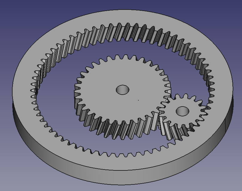
Tadaa!
In Part 2, we will look at compound planetary gears. In Part 3, we will write a script to animate these gears for visualisation.
Update:
The full, current code for planetary gear generation is now on GitHub:
https://github.com/codemakeshare/planetary_gears
Appendix
Here is the macro code in full:
# -*- coding: utf-8 -*-

# Macro Begin:
import FreeCAD
import InvoluteGearFeature
import PartDesignGui
import Part
import Part,PartGui
from math import *
from FreeCAD import Base

def makeGear(name, teeth, pressureAngle=20, module=1, helixAngle=10,  height=10, bore=0, external = True, position = Base.Vector(0.00,0.00,0.00), rotation =0, extrude=False):

	#Gui.activateWorkbench("PartDesignWorkbench")
	involute = InvoluteGearFeature.makeInvoluteGear(name+"_involute")
	involute.NumberOfTeeth = teeth
	involute.ExternalGear = external
	involute.HighPrecision = True
	involute.PressureAngle = pressureAngle
	involute.Modules = module

	involuteRadius = module * teeth /2.0

	doc = App.ActiveDocument

	if extrude:
		helix = doc.addObject("Part::Helix",name+"_helix")
		helix.Pitch = pi * 2.0 * involuteRadius * tan(pi*(90-abs(helixAngle))/180.0)
		helix.Height = height
		helix.Radius=involuteRadius
		helix.Angle=0.00
		if helixAngle>0:
			helix.LocalCoord=0
		else:
			helix.LocalCoord=1

		helix.Style=1
		helix.Placement=Base.Placement(Base.Vector(0.00,0.00,0.00),Base.Rotation(0.00,0.00,0.00,1.00))
		helix.Label=name+'_helix'
		App.ActiveDocument.recompute()

		sweep = doc.addObject('Part::Sweep',name)
		sweep.Sections=doc.getObject(name+'_involute')
		sweep.Spine=(doc.getObject(name+'_helix'),[])
		sweep.Solid=True
		sweep.Frenet=True

		sweep.Placement=Base.Placement(position, Base.Rotation(Base.Vector(0.0,0.0,1.0),rotation))
		App.ActiveDocument.recompute()
		Gui.ActiveDocument.getObject(name+'_involute').Visibility=False

		if external:  # make bore
			if bore>0:
				cylinder = doc.addObject("Part::Cylinder",name+"_bore")
				cylinder.Label = name+"_bore"
				cylinder.Radius = bore/2.0
				cylinder.Height = height+0.1
				cylinder.Placement=Base.Placement(position, Base.Rotation(Base.Vector(0.0,0.0,1.0),rotation))

				cut = doc.addObject("Part::Cut",name+"_ext")
				cut.Base = doc.getObject(name)
				cut.Tool = doc.getObject(name+"_bore")
		else: # make external ring
			cylinder = doc.addObject("Part::Cylinder",name+"_exthousing")
			cylinder.Label = name+"_exthousing"
			cylinder.Radius = involuteRadius+10
			cylinder.Height = height - 0.1
			cylinder.Placement=Base.Placement(position, Base.Rotation(Base.Vector(0.0,0.0,1.0),rotation))

			cut = doc.addObject("Part::Cut",name+"_ext")
			cut.Base = doc.getObject(name+"_exthousing")
			cut.Tool = doc.getObject(name)

	else:
		involute.Placement=Base.Placement(position, Base.Rotation(Base.Vector(0.0,0.0,1.0),rotation))
	App.ActiveDocument.recompute()

def makePlanetary(name, module=1.25, sun_teeth = 20, planet_teeth = 20, z_off=0, helix=10, height=10, extrude=True, bore=0):
	ring_teeth = 2*planet_teeth+sun_teeth
	mesh_distance = (sun_teeth+planet_teeth)*module/2.0

	planet_rotation = (1-(planet_teeth % 2))*180.0/planet_teeth
	ring_rotation = 180.0/ring_teeth + planet_rotation*planet_teeth/ring_teeth

	makeGear(name+"_sun", teeth = sun_teeth, pressureAngle=20, module=module, helixAngle=helix, height=height, bore=bore, position = Base.Vector(0.00,0.00,z_off), rotation =0, extrude=extrude)
	makeGear(name+"_planet", teeth = planet_teeth, pressureAngle=20, module=module, helixAngle=-helix, height=height, bore=bore, position = Base.Vector(mesh_distance,0,z_off), rotation =planet_rotation, extrude=extrude)
	makeGear(name+"_ring", teeth = ring_teeth, pressureAngle=20, module=module, helixAngle=-helix, height=height, bore=bore, position = Base.Vector(0.0,0.00,z_off), rotation =ring_rotation, external=False, extrude=extrude)
	App.ActiveDocument.recompute()

makePlanetary("first", sun_teeth = 34, planet_teeth = 16, z_off=0, helix = 15, height=10, bore=6)

Gui.SendMsgToActiveView("ViewFit")
This is great stuff. I just downloaded FreeCAD today. For this very purpose. To use it to model planetary gear trains – in order to understand how they work. And then I find this wonderful tutorial which you have put online. Thanks! It has helped “boot strap” me over the hurdle of learning “FreeCAD.” Since I am just a software guy with no ME or CAD experience, it was heartening to learn that a “parametric CAD package” like FreeCAD can basically be “programmed” to generate the objects you want. And this is a very nicely executed example of how to do just that.
Thanks! Glad it was useful!